


Oil Coolers
Overview
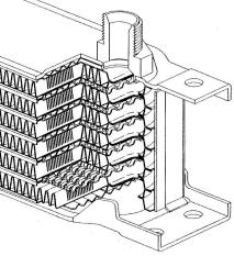
The cooler consists of a variable number of aluminium pressed plates forming oil ways and end tanks, the oil ways contain turbulators. These do not only break down boundary layer effects in the flow to obtain maximum heat dissipation without undue pressure drop but also, because they are brazed to both surfaces of the plates, hold them together under pressure. The oil ways are interspersed with aluminium strip louvered and formed into corrugations to provide airways.
 The design is beautifully simple and efficient and most suitable for mass production, but it is restricted to a 2" thickness and a limited amount of lengths. The secret of the success of the Mocal cooler is our insistence on the highest standards of build quality allied to a rigorous inspection system. In particular the attention paid to the accuracy of the pressing tools to ensure the closest contact of the plates during the "Nocoloc" brazing process ensures our superiority over look-a-likes from the Far East.
Maximum working pressure on the standard range of coolers is 10 bar (150psi) although each cooler is tested to 11.5 bar (170psi) this is adequate for all but the most arduous motoring applications, however some customers prefer a higher pressure rating, for instance where the pressure by pass valve does not provide enough protection as in high rpm in cold start up conditions or on dry sump installations.
Heavy Duty
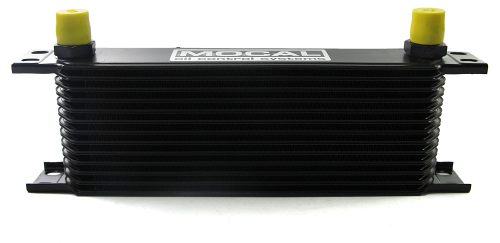
We have introduced a heavy duty (HD), 12bar (180psi)working pressure, version of the cooler which is dimensionally similar but has aluminium castings between the plates, on the standard cooler this is the weakest point where they are unsupported by fins or turbolaters, there is also thicker material in some areas. These coolers are about 18% heavier.
Weights and Measurements
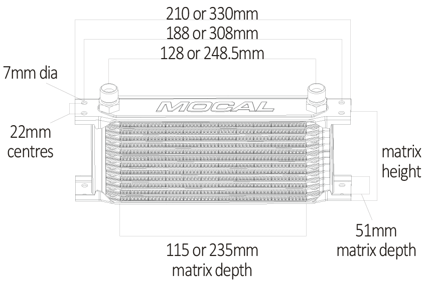
The coolers are available in various heights and two widths, 115mm matrix or 235mm matrix but only one, 51mm, front to back measurement. The height of a cooler is usually r ferred to in rows, these are the number of oilways including top and bottom plates which carry oil.
| 115mm Matrix | 235mm Matrix | ||||||
|---|---|---|---|---|---|---|---|
| Number of Rows | Height (mm) | Capacity (litres) | Weight (kg) | Capacity (litres) | Weight (kg) | ||
| Standard | Heavy Duty | Standard | Heavy Duty | ||||
| 7 | 53 | 0.08 | 0.31 | 0.38 | 0.14 | 0.53 | 0.49 |
| 10 | 77 | 0.12 | 0.39 | 0.50 | 0.20 | 0.71 | 0.75 |
| 13 | 100 | 0.16 | 0.48 | 0.63 | 0.26 | 0.88 | 1.06 |
| 16 | 124 | 0.19 | 0.60 | 0.74 | 0.32 | 1.06 | 1.28 |
| 19 | 147 | 0.23 | 0.67 | 0.85 | 0.38 | 1.24 | 1.49 |
| 25 | 194 | 0.30 | 0.84 | 1.07 | 0.50 | 1.60 | 1.94 |
| 34 | 265 | 0.41 | 1.15 | 1.40 | 0.68 | 2.14 | 2.58 |
| 44 | 344 | 0.53 | 1.46 | 1.91 | 0.88 | 2.73 | 3.27 |
| 50 | 390 | 0.60 | 1.63 | 2.05 | 1.00 | 3.09 | 3.72 |
| 60 | 460 | - | - | 2.25 | 1.30 | 3.69 | 4.45 |
Performance
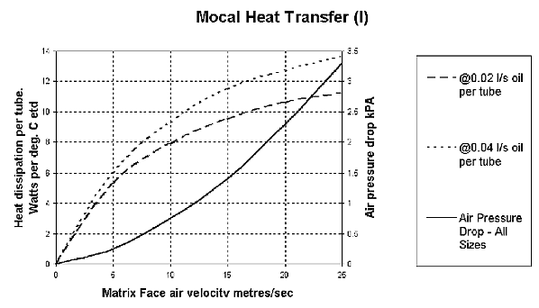
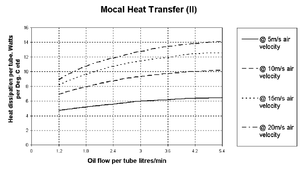
Interpreting The Graphs
- Calculate oil flow per tube. Usually an unknown, the oil flow through the engine can only be measured using a flow meter.
(Example: 29 litres/min through 16 row cooler → 29 / 16 = 1.8 litre/ min ) - Calculate etd (extreme temperature difference).
(Example: oil in to cooler at 120° C - Ambient at 25° C \ 120 - 25 = 95). - State matrix air velocity. Again, an unknown depending on cooler position, whether ducted etc, typically a fifth of the available air would go through the cooler.
(Example: road speed 112mph divide by 2.25 to get 50 metres/sec divide by 5 gives 10 m/s m.a.v.) - From the graph we find we are dissipating 8.8 watts per tube per °C etd.
- Calculate total heat dissipated.
(Example: 8.8 x 16 (tubes) x 95 (etd) = 13376 watts at 13.4 kilowatts) - Calculate oil out of cooler temperature which is arrived at by deducting the heat dissipated multiplied by a constant of 39 divided by the oil flow rate from oil temperature in to cooler
(Example: 120 - (13.4 x 39 / 29) = 102°C)
Setrab have no graphs available, but do have a comprehensive computer programme to work out individual cases, please give us the parameters and we will provide a print out.
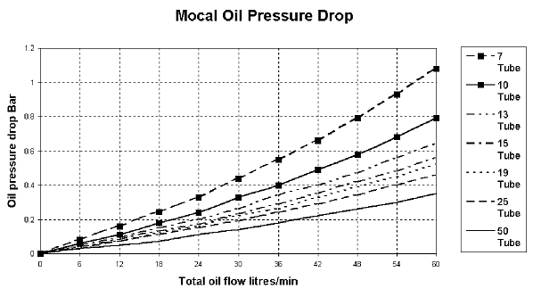
Graphs for oil pressure drop are self explanatory, however please note that the oil in the Laminova graph is at 120° C, the oil in the Mocal is at 100° C and therefore thicker, so meaningful comparisons are difficult.
KPa to psi multiply by 0.145
Bar to psi multiply by 14.5